Appearance
Creating a Macro
Before trying to create a macro, it is important to realise that a circuit designed with Digital Works can have two visual states associated with it. These are called the implementation and interface views.
The implementation view provides a window in which the functionality of the circuit is defined. For example, by wiring four flip flops together, a four bit counter can be created. The inputs and outputs of the implementation view can then be associated with the inputs and outputs of the interface view.
The interface view can be considered an abstraction or 'black box' hiding the circuit's implementation. The relationship between these two views is shown below:
Implementation View
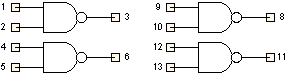
Interface View

The implementation view is put together using exactly the same techniques used to design a circuit with Digital Works. Use the Template Editor to design the interface view. The Template Editor also enables communication paths between a circuit implementation and its interface to be established using pin associations.
To create a macro, you will need to carry out the following sequence of operations:
Step 1
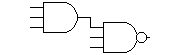
In Digital Works, design and test the circuit you wish to use. In this example, we are going to create a 5 input NAND gate macro. The implementation of this circuit is shown below.
Step 2
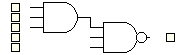
Place a number of macro tags onto the circuit workspace. These 'tags' should represent the inputs and outputs of the circuit. In this example, we have five inputs and one output.
Step 3
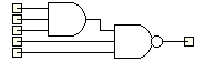
Ensure that all macro tags are wired up to relevant parts of the circuit, as shown here.
Step 4
Right click on a macro tag and select the Template Editor… option.
Step 5
In the Template Editor, use the drawing tools to design the interface view. Remember, the interface view is the image that will be seen when a macro is embedded into a circuit, so try and keep it neat and tidy.

Step 6
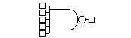
Now add some template pins. Template pins enable wires to be connected to the final macro, so make sure you put them in the correct place. For the 5 input NAND example, these are shown below.
Step 7
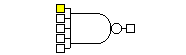
Right click on a template pin and select the Associate with Tag option. This will link the circuit macro tag you originally selected in the implementation view with the template pin of the interface view. Once an association has been made, the pin colour changes to yellow. Pins that are coloured red mean that they have already been associated to another pin object and cannot be reused.
Step 8
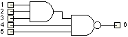
Close the Template Editor. You should now see that the macro tag has now a number attached to it. In this example, it is the number one. This means that the macro tag has been linked successfully to the first interface pin contained in the template editor.
Step 9
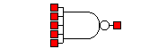
Finally, associate all the other macro tags with template pins. Right click on a macro tag, and select the Template Editor option. When in the Template Editor, right click on the pin you want to link to and choose Associate with Tag. Repeat this process until all the macro tags have been associated with all the template pins.
The final interface view should now look like this:
And the implementation view will look something like this:
Before you save the final macro to disk, you can choose whether or not you want the template pins to be visible when the macro is embedded in a circuit. In the above example, we do not want the pins to be visible, as this would spoil the look of the 5 input NAND gate graphic. If this is the case, ensure that the Display Template Pins button on the Template Editor toolbar is in the up position before saving (don't worry if you forget, you can always change it later). For some types of macro e.g. integrated circuits, it is usually best to leave the button in the down position.
Macro Tags
Macro tags are special objects that define the inputs and outputs of a macro's implementation circuit. They serve as the connection points between the implementation view and the interface view. Place macro tags from the main toolbar and wire them to the relevant parts of your circuit.