Appearance
 Adding Memory
The memory icon enables you to place either a Random Access Memory (RAM) or Read Only Memory (ROM) object into a circuit. Both the number of address lines and the number of data lines are user definable.
Placing a Memory Device
To place a memory device onto the workspace, select the memory icon and move the mouse into the active view. Press the left mouse button to invoke the select memory device window, as shown below.
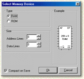
Use the above window to set the type of memory you want (ROM or RAM) and also the number of address and data lines you require.
Control Pins
In addition to the address and data lines, the memory device also has two further inputs:
 R/W̄ (Read/Write) — For a RAM device, the information on its data lines will be written to memory if the R/W̄ pin is low. Setting the R/W̄ pin to high will perform a read operation. The value on the address lines selects the memory location required for reading or writing. If a ROM device is selected, this pin is disabled as only read operations can be performed.
 C̄S̄ (Chip Select) — The C̄S̄ pin is used to enable or disable a memory device. If the C̄S̄ pin is low, the device is enabled. If C̄S̄ is high, the device is disconnected from the data bus.
Editing Memory Contents
You can change the contents of the memory device by right clicking it with the mouse and choosing Edit Memory Contents. This will invoke the Memory Contents window. You can also use the Memory Contents dialog window to view the internal state of a memory device when a circuit is being run.