Appearance
Logic History Window
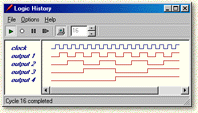
Sometimes, just observing the outputs of an LED is not enough. We need to record a history of the circuit's inputs and outputs. Digital Works provides a logic history function that can be used to record and display both inputs and outputs.
Adding Signals to the Logic History
By right clicking on a sequence generator, clock or LED object with the object selector tool, you can activate the Add To Logic History function. When this is selected (denoted by a check mark on the pop up menu), all input or output is copied to a history buffer.
Viewing the Logic History
To view the logic history window, select Tools from the main menu and select the Logic History Window... option.
Naming Signals
It is also possible to name LED, or rename clock and sequence generator objects, by selecting Text... from the selected object's pop up menu. This name can be used to identify the object in the Logic History Window. You can reposition text to the left, right, top or bottom of a device by selecting the Text Style option from the pop up menu.
Simulation Controls
The Logic History Window contains a copy of the run, stop, pause and step icons to allow you to step through the simulation from the logic history window.
Additional Toolbar Options
Toggle Display Mode

Used to display the output as a waveform (shown above) or as binary sequences of 1s and 0s.
Clock Cycle Range

Use the clock cycle range spin button to change the amount of history that is displayed in the logic history window.