Appearance
Numeric Output

The Numeric Output device can be used to display the output of a circuit as a binary, hexadecimal or decimal number.
Placing the Device
To place a device into a circuit workspace, select the icon using the object selector tool and move the mouse into the active view. Press the left button to fix the device at the required location. At this point, the Numeric Output window is invoked, as shown below.
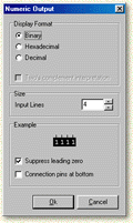
Display Format
The display format option allows you to choose if the number is to be displayed in binary, hexadecimal or decimal notation. If the decimal option is selected, you can also choose whether you want the device to interpret the binary value on its input lines as two's complement (a signed binary representation where the most significant bit indicates the sign).
Number of Input Lines
The size of a number that the device can display is defined by the number of input lines it has:
| Input Lines | Unsigned Range | Two's Complement Range |
|---|---|---|
| 4 | 0 to 15 | -8 to +7 |
| 8 | 0 to 255 | -128 to +127 |
| 16 | 0 to 65535 | -32768 to +32767 |
Digital Works allows the number of input lines to be set from 2 to 16.
For non-negative integer values, the range is 0 to 2ⁿ - 1, where n is the number of input lines.
For two's complement, the range is -2ⁿ⁻¹ to +2ⁿ⁻¹ - 1, where n is the number of input lines.
Additional Options
- Suppress leading zeros — dims any zeros preceding the display number.
- Connection pins at bottom — displays the input lines at the bottom of the device.
Editing Properties
When a numeric display device has been embedded into your circuit, you can edit its properties by right clicking on the device using the object selector tool and choosing the Properties... option.
Note
You cannot alter the number of input lines after placement. Ensure that the correct number of inputs has been selected before making any connections.
You can also change the color of the numeric elements by selecting the Change Color... option.