Appearance
 JK Flip Flop
The JK type flip flop is one of three types of flip flop, also known as bistable devices (a device with two stable states), supported by Digital Works, the others being the D type and RS flip flops. The JK flip flop is a master-slave (master-slave architecture) clocked device whose output is enabled on the falling edge (edge-sensitive triggering) of a clock signal.
Truth Table
| J | K | Comments |
|---|---|---|
| 0 | 0 | No change in the outputs |
| 0 | 1 | RESET action. Q = 0, Q̄ = 1 |
| 1 | 0 | SET action. Q = 1, Q̄ = 0 |
| 1 | 1 | Toggle Q and Q̄ |
The above table assumes that the device is being clocked. That is, the 'clock' input of the device is changing from 0 to 1, 1 to 0 and so on. The clock input can be connected to the output of any other type of device. This is particularly useful for creating certain types of sequential logic elements such as counters, where the Q output of one JK flip flop can feed the 'clock' input of another JK device. If the 'clock' input does not change state, then the Q and Q̄ outputs will remain stable.
It can be seen that the JK flip flop behaves in a similar manner to the RS flip flop. Its J input sets Q = 1 and its K input resets Q = 0. However, unlike the RS flip flop, setting both its J and K inputs to logic high will 'toggle' the state of its output.
Clear and Preset
In addition to its J and K inputs, the device has two further inputs, as shown below.
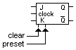
Setting the clear input to logic high will reset the device. Setting the preset input to logic high will set the device. The device does not have to be clocked for clear and preset to work.
Placing the Device
To place a flip flop object into a circuit workspace, select the appropriate icon with the object selector and move the mouse into the active view. Press the left mouse button to fix the device at the required location.